Piece Properties
You can use the Piece Properties option, when you want to view/edit information about pieces.
 Note:The
Piece Properties is dynamic according to the element you have selected;
therefore the fields are different for elements (piece, button, dart,
pleat, etc.) For more information, see Piece/Element
Properties
Note:The
Piece Properties is dynamic according to the element you have selected;
therefore the fields are different for elements (piece, button, dart,
pleat, etc.) For more information, see Piece/Element
Properties
Icon & Location
-
PDS Menu: Edit > Piece Properties *or double-click on a piece, button, dart, etc. and the Piece Properties panel displays)
To view the Piece Properties:
-
Select a piece in the Working Area, then double-click.
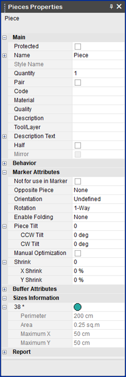
The Pieces Properties panel appears (according to the element you clicked on) . This panel doesn't include the Zone Properties.
-
View the fields as follows:
|
Field |
Description |
|
Main Task Pieces |
If multiple pieces are selected, this field indicates which pieces will be affected by the change. Note that you can set the Task Pieces to All pieces even if only one piece is selected on the Working Area. If the fields of several pieces don't match, Different is displayed in this field. If you change a field, e.g., the Name field, this will influence all the pieces indicated in the Task Pieces. |
|
Protected |
Protects the piece's geometry from being edited. All the fields in the piece properties are grayed in order to show that the piece is in protected mode. On the right side of the status bar, 'Protected' is displayed.
|
|
Name |
|
|
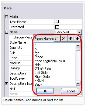
Unique Piece Name |
The unique ID of a piece. (This field cannot be changed.) |
|
Style Name |
This feature is used for converted files which require extra information. To edit:
|
|
Quantity |
Sets the Quantity of the piece(s). |
|
Pair |
Sets the piece(s) as Pair. |
|
Code |
Displays the piece's unique code. |
|
Material |
Displays the material that is assigned to the piece. If you want to use more than one material per piece, you can enter numerous materials using a comma. For example, wool, lycra, etc. You can then set the materials per piece in the Marker using the Marker Order dialog. For more information, see Order For Marker Making. |
|
Quality |
Displays the quality of the piece. |
|
Description |
Displays free text for the description of the piece. |
|
Tool/Layer |
Sets the piece(S) as Tool/ Layer. |
|
Description Text |
Sets the properties of the Piece Information Text. Show or hide this text through the View & Selection. |
|
Adjust |
Sets the font size, angle and centered field according to the values set in the Preferences. |
|
Font Size |
Sets the font size of the Piece Information Text.
|
|
Angle |
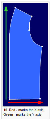
A Zero angle rotates the description parallel to the X Axis A 90 degree angle rotates the description parallel to the Y Axis
|
|
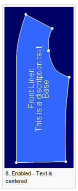
Centered |
Check this field when there are several Piece Information Texts. The texts are then centered around the middle of their Bounding Box.
|
|
Half |
Indicates if the piece is set to Half. Show or hide the symmetrical half through the View & Selection. |
|
Mirror |
Indicates if the piece is Mirror symmetrical. |
|
Behavior |
|
|
When enabled, Auto-Reseam is not applied to the piece. |
|
|
Lock Auto Update Notch |
When enabled, Auto Update Notch is not applied to the piece's seam. |
|
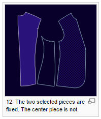
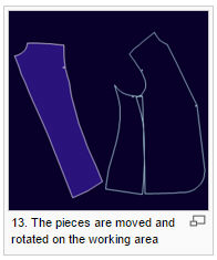
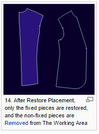
Fixed Placement on Working Area |
Saves the piece's position on the working area, to be used by Restore Placement.
|
|
Marker Attributes |
|
|
Select this checkbox if this piece/s should not be used in the Marker. |
|
|
Opposite Piece |
If you require an opposite piece, select the option of the opposite piece from the drop-down list |
|
Orientation |
Sets the orientation of the pieces. |
|
Rotation |
Sets the rotation of the pieces. |
|
Enable Folding |
Sets the folding of the pieces. |
|
Piece Tilt |
Sets the piece's tilt that is allowed in the marker |
|
CCW Tilt |
Enter the required counter-clockwise tilt in degrees. |
|
CW Tilt |
Enter the required clockwise tilt in degrees. |
|
Manual Optimization |
Select this checkbox, if you want to manually define the Marker optimization. |
|
Shrink |
If shrink values were entered, the overall shrink value appears here. |
|
X Shrink |
Enter the X shrink percentage. |
|
Y Shrink |
Enter the Y shrink percentage. |
|
Buffer Attributes |
|
|
Buffer Size |
Enter the buffer size required
|
|
Buffer Location |
Select the location where you want the buffer to appear. |
|
Sizes Information |
|
|
Size |
Displays the size defined for the pieces. |
|
Perimeter |
Displays the defined perimeter. For example 30+30+20+20=100cm
|
|
Area |
Displays the defined area. For example, 30*20=600sq.cm
|
|
Maximum X |
Displays the piece's maximum X distance.
|
|
Maximum Y |
Displays the piece's maximum Y distance.
|
|
Report |
|
|
Save to File |
Creates the report as a text file. |
|
|
Prints a more detailed report (with the piece's images). |

 See also: Piece Menu