Creating the Marker File
Once you have your PDS file prepared with textures and your piece geometry
saved in a PDF file, you can create a Marker file.
In the Marker
Definitions
dialog, the Waste Limits settings at
the bottom of the dialog should be assigned to sufficiently place cut
marks outside of pieces and the QR code. The size of waste limits should
be greater than the sum of the cut marks diameter and offset from cut
line parameters defined during the Print & Cut file generation. When
the QR code should be placed, the waste limit for the left side should
also be greater than the 6 cm left for the QR code.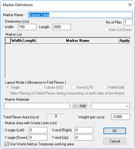
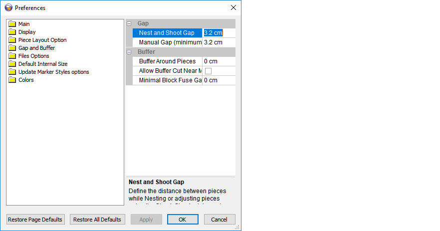
The Gap between
pieces is specified in the Preferences prior to the nesting and should
also be defined, taking into account cut marks placement. The Gap should
be greater than the sum of the cut mark diameter and doubled offset from
the cut lines distance. In such a way, the Gap between pieces will be
enough to place the cut mark between two adjacent pieces.
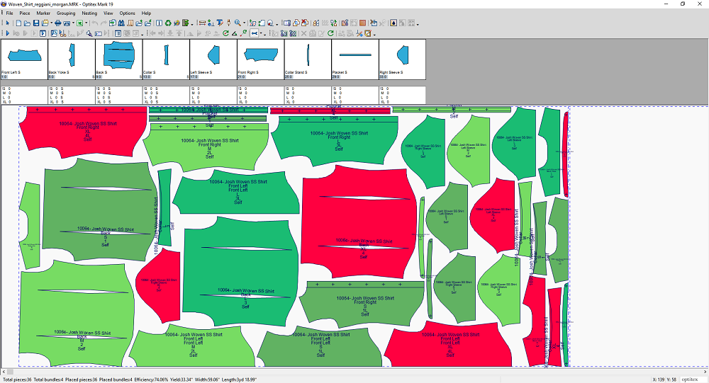
Now you can create a Marker file in the usual way, taking into account
the correct values mentioned above - and then perform the nesting. Once
this is done, you can run the Print & Cut.
Now you can move on to the last step, Creating
a Print & Cut File.
 See also: Print & Cut