Mark-10 Tension Meter Assembly

Perform following actions to assemble the Mark-10 machine

  • ClosedMounting

    Place the stand on a clean, flat and level work area free from vibration.

    For the vertically oriented ESM303, it is recommended to mount the stand to a work bench via screws fastened into the underside of the base. Failure to properly mount the test stand may make it more vulnerable to tipping, especially if a column extension is used. This can cause a hazardous situation.

  • ClosedMounting the control panel

    To avoid damage during shipment, the control panel and mounting bracket are packaged separately. Follow these installation instructions:

    1. Install the mounting bracket with the spring joint to the column utilizing one 1/4-20 screw.

    2. Install the control panel to the spring joint.

    3. The viewing angle may be adjusted by loosening the spring joint, positioning the control panel, and re-tightening the joint.

  • ClosedLimit Switches

    Upper and lower limit switches are supplied to stop travel in both directions. The limit switch thumb screws are shipped, banded together, as illustrated below:

    Remove the rubber band and instructional tag before use. Refer to later sections for more detailed information about limit switches.

  • ClosedConnections and Outputs

    The following connections and outputs are supplied in the rear of the test stand, as shown in the illustration below:


    • USB connector. Outputs force only or force and travel data (optional) via USB. Also allows for PC control (optional).

    • Auxiliary limit switch connector. For interfacing an external limit switch, such as an interlock for a machine guard door. A pin diagram is shown in the next sub-section.

    • Control panel cable connector. Plug the cable into this connector.

    • Power switch. Refer to the Connecting Power sub-section for important safety information.

    • Power plug receptacle. Plug the power cord in here. Refer to the Connecting Power sub-section for important safety information.

  • ClosedInstalling the 09-1158 USB Cable

    Plug one end of the USB cable into the corresponding connector. Install the USB driver before physically connecting the tester to a PC with the USB cable.

  • ClosedInstalling a M5-5 Force Gauge

    Once the test stand is in a stable and secure position, install a force gauge by mating the dowel pin in the force gauge mounting plate with the blind hole in the rear of the force gauge’s housing. Use the four thumb screws to secure the gauge. Grips and fixtures may be threaded onto the force gauge and test stand base.

    It is important to not put too much pressure at any time on the force gauge as it is very sensitive and can easily be damaged.

  • ClosedInstalling the 09-1214 Interface Cable

    If using test stand functions requiring communication between the force gauge / indicator and test stand, such as data output, overload protection, preload, etc., connect the interface cable between the instrument’s connector and the crosshead’s connector.

  • ClosedConnect control panel cable

    Plug one end of the control panel cable into the control panel cable connector in the rear of the machine.


  • ClosedInstall G1015-1 Grips

    Install G1015-1 Film & paper grip, 3" following these installation instructions:

    1. Install the lower grip on the base table.

    2. Install the upper grip on the threaded loading shaft of the force gauge.

    3. Make sure that both grips are installed parallel to each other as shown below.


  • ClosedConnecting Power to M5-5 Force Gauge

    The gauge is powered either by an 8.4V NiMH rechargeable battery or by an AC adapter. Since these batteries are subject to self-discharge, it may be necessary to recharge the unit after a prolonged period of storage.

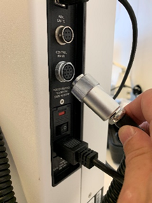
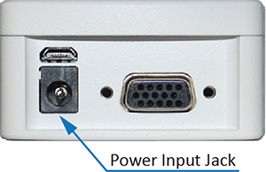
    Plug the accompanying charger into the AC outlet and insert the charger plug into the receptacle on the gauge (refer to the illustration below). The battery will fully charge in approximately 8 hours.


    Important: Do not use chargers or batteries other than supplied or instrument damage may occur.


    If the AC adapter is plugged in, an icon appears in the lower left corner of the display, as follows:  

    If the AC adapter is not plugged in, battery power drainage is denoted in a five-step process:

    1. When battery life is greater than 75%, the following indicator is present:

    2. When battery life is between 50% and 75%, the following indicator is present:

    3. When battery life is between 25% and 50%, the following indicator is present:

    4. When battery life is less than 25%, the following indicator is present:

    5. When battery life drops to approximately 2%, the indicator from step 4 will be flashing. Several minutes after (timing depends on usage and whether the backlight is turned on or off), a message appears, “BATTERY VOLTAGE TOO LOW. POWERING OFF”. A 4-tone audio indicator will sound, and the gauge will power off.

    For more information about power and battery refer to the Series 5 Digital Force Gauges User’s Guide available at www.mark-10.com.

  • ClosedConnecting Power to ESM303 Stand

    Plug one end of the power cord into its receptacle at the rear of the stand and the other end into a wall outlet with local earth ground (3-prong connector). Use a local electricity adaptor, if necessary.

    Before turning the power on, the following safety checks and procedures should be performed:

    1. Never operate the test stand if there is any visible damage to the power cord or the test stand itself. The ESM303 is powered by 110V/220V. Any contact with this high voltage can cause serious injury or even death.

    2. Ensure that the test stand is kept away from water or any electrically conductive liquids at all times.

    3. Make sure the electrical outlet powering the test stand has local earth ground (3-prong connector).

    4. The test stand should be serviced by a trained technician only. Power must be disconnected before the column covers are removed.


Related links