Editing Shaders
You can use shaders to change the visual representation of the materials that are used when draping the cloth in 3D. This allows you, for example, to produce a bump effect on your cloth, add different images such as logos, or change the background layer. You build shaders in connection to the variants and articles created in the Shader Manager; therefore, the shaders are defined in layers and have a dependency according to their layer.
You first need to create Variants and Articles before you can edit the shaders. For more information, see Adding Textures to your Pattern.
To edit shaders:
-
Open the Shader Manager (go to Windows > 3D Windows > Shader or press 9 on your keyboard).
The Shader dialog contains the following toolbar:
![]()


 /
/
-
While standing in the Shader Manager, select either a Variant or Article.
If you are defining a Variant, the following fields can be modified:
|
Field |
Description |
|
Shader/Type |
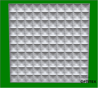
From the drop-down list, select the Shader Material. The Shaders are automatically included in the installation files. Most of the Shaders will only appear when in HQR or PR3D mode. Here is an example of the Waffle Shader in Open GL (regular simulation)
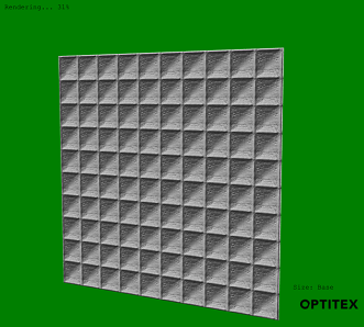
Here is an example of the Waffle Shader after turning on HQR:
Here is an example of the Waffle Shader after turning on PR3D:
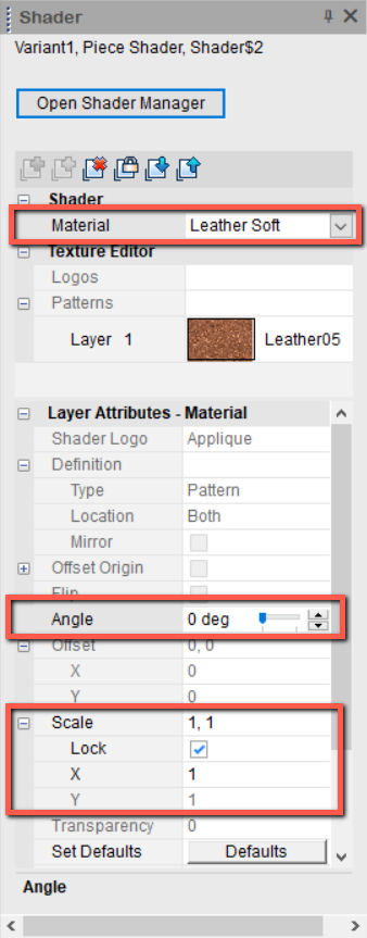
Starting from O/18, you can change Shader attributes when standing on the Shader Material:
Notice the Angle and Scale fields are enabled allowing you to edit the angle and scale of the shader (not only textures, logos). See Angle and Scale below for more information about how to edit. |
|
Texture Attributes/ Transparency |
Use to change the transparency of the shader. You can either manually enter a value or use the slider to select a level of transparency. Here is an example of the Waffle shader at 40 transparency.
|
|
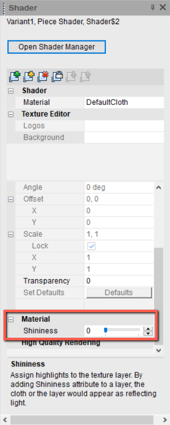
Material/Shininess |
Use to change the shininess of the shader. You can either manually enter a value or use the slider to select a level of shininess. |
If you are defining an Article, the following fields can be modified.
 Note:All of the changes you make to the Shaders are also reflected in the 2D
environment.
Note:All of the changes you make to the Shaders are also reflected in the 2D
environment.
|
Field |
Description |
|
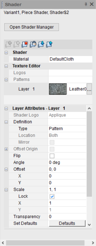
Texture Editor |
|
|
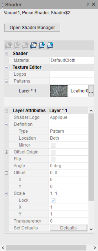
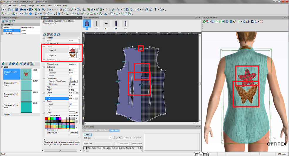
Logos |
Once you add a layer, the Layer appears with a number and a thumbnail of the image as follows: 
|
|
Background |
You can only have one background and it is defined as the Variant. |
|
Texture Attributes |
These attributes are dynamic according to the logo or pattern you have selected.
As a best practice, if you want a different texture on a specific piece, you should create a copy of the shader make changes to the texture attributes and then apply the shader to the specific piece. |
|
|
If you are creating a PR3D logo you can define the type of logo:
Applique:Use if you want the logo to appear as a separate entity on the cloth.
Printed: If you want the logo to appear printed inside the cloth.
|
|
Definition |
|
|
Type |
Logo - Appears as a logo on the cloth.
Splitting Logo - Currently not supported. Repeat X Logo - Spreads the logo across the cloth horizontally.
Repeat Y Logo - Spreads the logo across the cloth vertically.
Pattern- Creates a tiling look. Use this option for Lace.
|
|
Location |
This field is used when you have paired pieces. You must make sure you set this up correctly in the Piece Properties first. Then you can select the location of the logo. |
|
Mirror |
If your piece is Paired, select this checkbox, if you want to create a mirrored look of the logo..
|
|
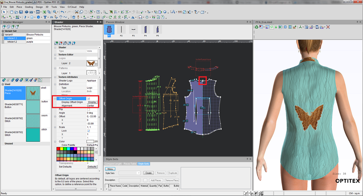
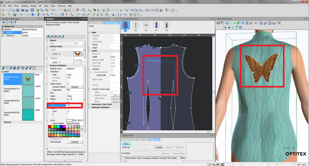
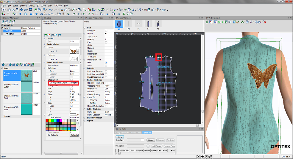
Select this checkbox, if you want to define a reference point/button for the logo. By default, all logos appear in the center of the piece. With this option you can assign a new point thus letting you change the location of the logo in accordance to a point and not the piece. |
|
|
Flip |
Select this checkbox if you want to flip the logo:
|
|
Adjust the angle of the logo either by entering a value manually or by using the slider to adjust the angle. Here is an example of the logo at 90 degrees:
|
|
|
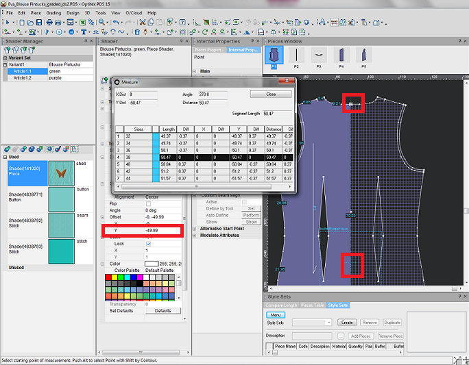
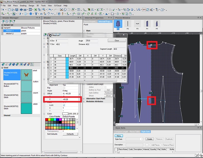
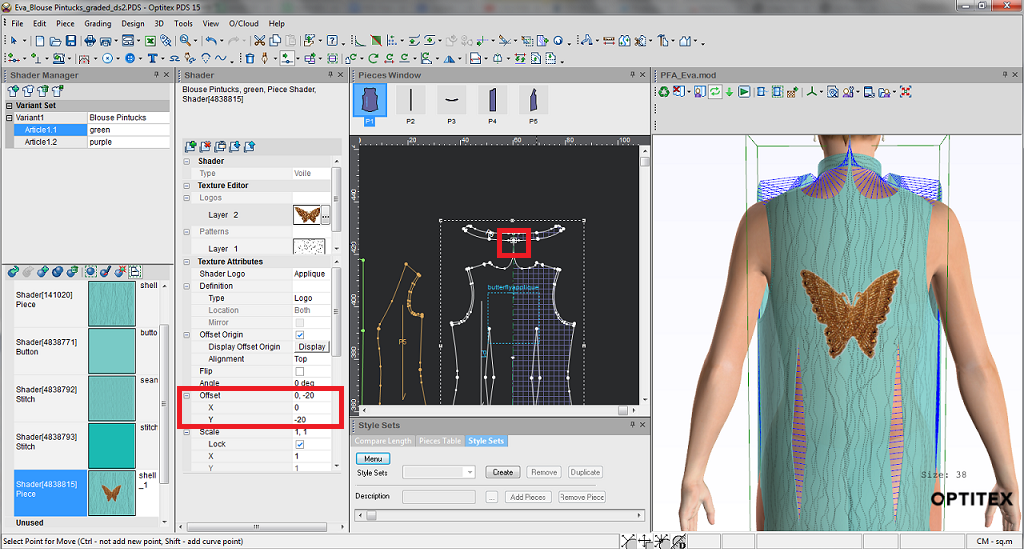
Offset |
Change the offset of the logo (from the center 0,0). You can either enter a ratio or manually change the X and Y values. |
|
Change the size of the logo using a ratio (X and Y). 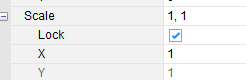
This is how it will look like working units is on: 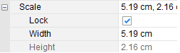
|
|
|
Lock |
Select this checkbox, if you want to skew the image and not have it proportional.
|
|
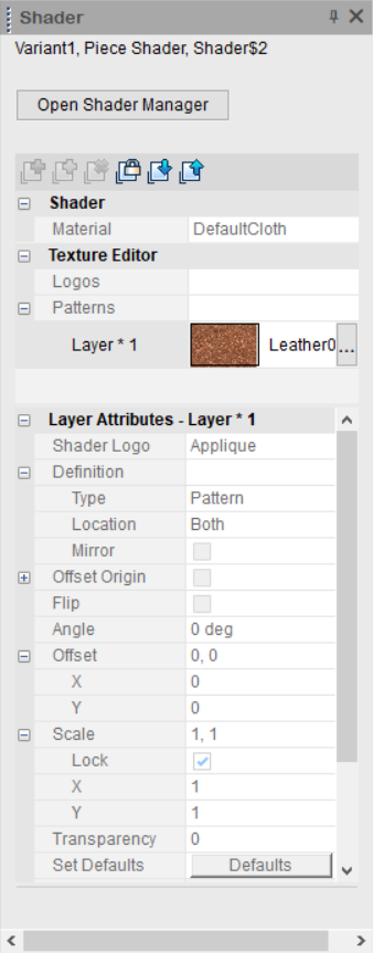
Color |
Select a color via one of the following methods: Use the custom made Color Picker Select a color from the color palette. Upload your own color palette (.aco) |
|
Color Palette |
Here you can define the color palette that is used for your shaders. You have a few different options here: 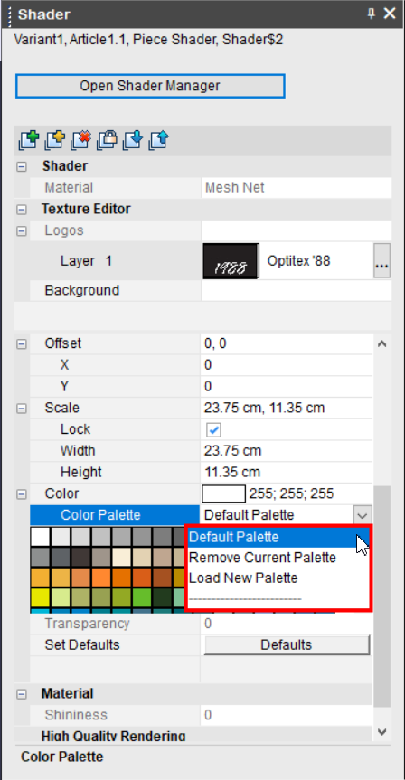
Default Palette: Select if you want to use the default palette (provided by Optitex). Remove Current Palette: Select if you want to remove the current color palette and you want to use a different palette. Load New Palette: Select
when you want to upload your own color palette. You can use the
color palettes that are available in the sample pack, or upload
your own.
|
|
Transparency |
This is only available for Background layers (variants). Using the slider, set the transparency you require.
|
|
Set Defaults |
Click this button to go back to the default properties. |
|
Material |
|
|
Shininess |
This is only available for Background layers (variants). |
|
High Quality Rendering |
Currently under development. |

 See also:Adding Shaders and Textures