Preparing Logo Placement Schemes and 3D images
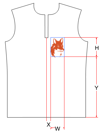
The Tech Pack Essentials feature allows you to generate images illustrating logo placement. For every certain logo placed on a piece, a logo placement scheme could be generated and added to the tech pack. Such logo placement schemes provide you with the geometry of the piece where the logo is placed, logo bounding box and logo image. The logo placement scheme may contain dimensions describing the logo position; such dimensions are defined and managed using the Measurement Chart functionality.
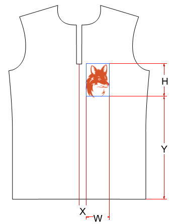
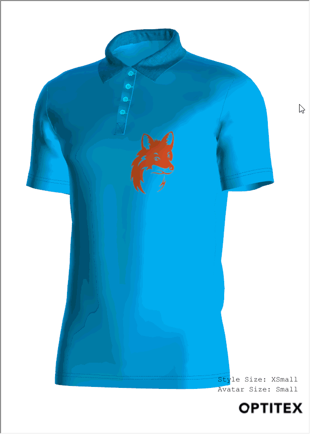
Besides logo placement scheme, an additional 3D logo image could be generated to provide you with better illustration of the logo position and orientation on simulated & rendered model.
To get logo placement schemes and 3D images in tech pack, several preparation steps should be performed.
To prepare logo placement schemes:
In Shader Manager property panel, click the Create Logo Internal button.
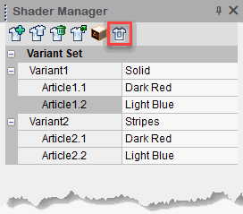
This button automatically generates internals providing you with bounding box geometry of logo images used through articles. When this button is clicked, all distinct logo images placed on pieces (by logo images are meant those images where the Definition Type is set to Logo) are detected through articles. For every such distinct logo image placed on a certain piece, the bounding box internal is generated as shown below.
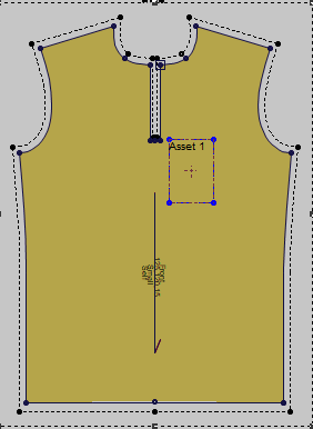
In addition to it, for every such distinct logo image placed on a certain piece, a new Measurement Chart is created named as logo_<logo name>_<piece name>, where the logo_ is a prefix, <logo name> is the name of the logo as it appears in the Shader definition, <piece name> is the name of the current piece.
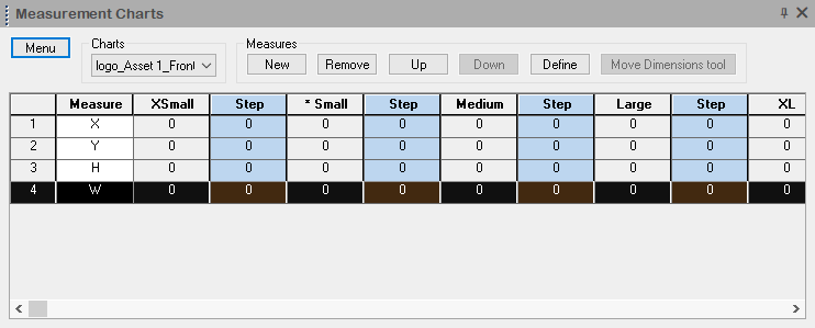
By default, such a measurement chart contains four measures: X, Y, W, and H dedicated to handle the logo position (X and Y) and logo size (H and W). By default, these measures are defined with no assignment to the piece geometry. Such an assignment should be performed manually using regular measurement chart functionality.
Use regular measurement chart functionality and assign measures to the respective bounding box internal.
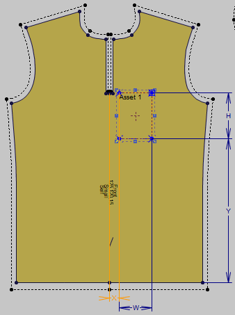
The resulted image of the piece geometry where the logo bounding box is applied together with placed dimensions is spooled to the generated tech pack document.
Note:In the generated tech pack document, such a logo placement scheme could be combined with the logo image providing you with the realistic logo display within the bounding box.
Rotate and zoom the cloth model to see the current logo.
Using Custom Views dialog box, create a new view named as logo_<logo name>_<piece name>, where the logo_ is a prefix, <logo name> is the name of the logo as it appears in the Shader definition, <piece name> is the name of the current piece.
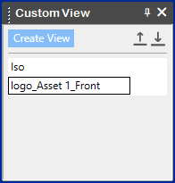
A snapshot image generated using the created view will appear in the generated tech pack.