Internal Contour Properties
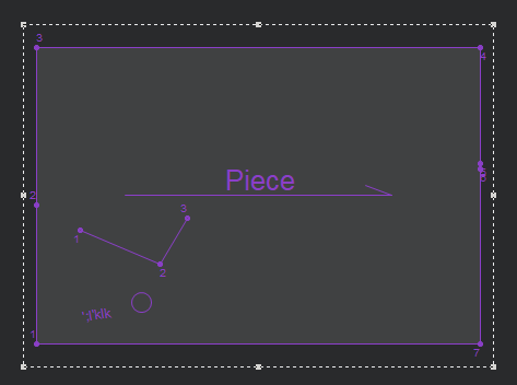
You can use the Internal Contour Properties dialog when you are creating/modifying an internal contour in your pattern.
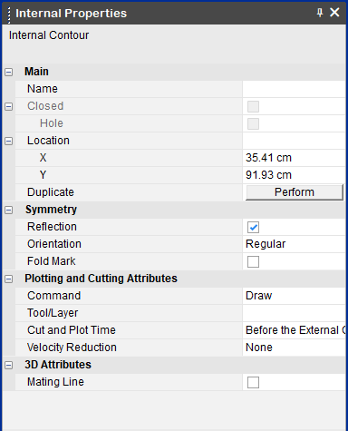
View the fields as follows:
|
Field |
Description |
|
Main |
|
|
Name |
Enter the name of the internal segment. You can display the name via the View and Selection dialog. |
|
Closed |
If selected, sets the internal as closed. Open
Closed
|
|
Hole |
If selected, sets the internal segment as a hole
|
|
LockAuto Reseam |
If Hole is selected, this field appears and allows you to NOT automatically reseam the segment if the contour changes.
|
|
Lock Auto Update Notch |
If Hole is selected, this field appears and allows you to NOT automatically update notches if a notch is added or changed. |
|
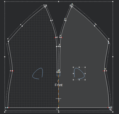
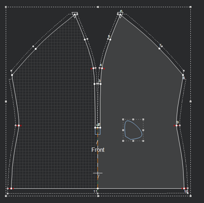
Location |
Sets the location of the internal bounding box's center point from the 0,0 point. You can enter the X and Y values to change the location. |
|
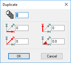
Duplicate |
Click Perform to open the Duplicate dialog:
This allows you to create a copy of the internal segment and decide on the X, Y location and angles. |
|
Symmetry |
|
|
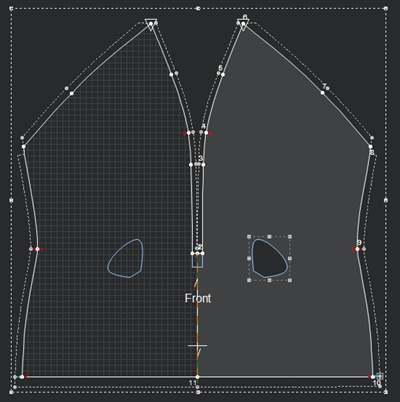
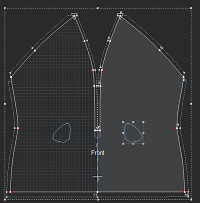
Reflection |
If the piece is set to half, this enables the internal segment to be symmetric on the other side. Not Symmetric
Symmetric
|
|
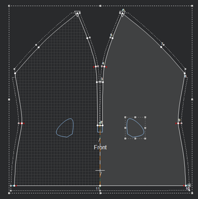
Orientation |
Determines if the internal segment will be cut/plotted in all instances of the piece. Make sure the piece is defined with an even quantity, and that the orientation is set to Left/Right. Regular: On the piece Left Only: On the left Right Only: On the right |
|
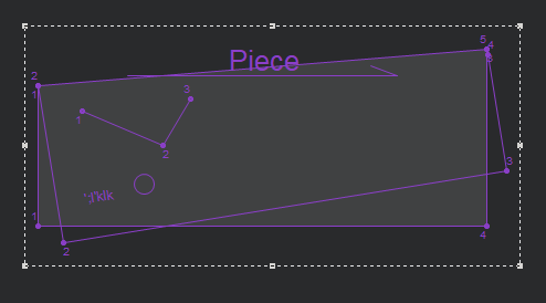
Fold Mark |
Select this option, if you want the internal object to be located on the side of the folded piece after unfolding. Note: If you have more than one object you must select each object one by one and turn on/clear the checkbox. You cannot select the checkbox for all objects at once. Fold In
Fold Out Notice the internal objects appear on the same side of the piece after folding
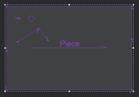
Clear this option, if you want the internal object to be located on the opposite side of the folded piece after unfolding: Fold In
Fold Out Notice the internal objects appear on the opposite side of the piece and unfolding
|
|
Plotting and Cutting Attributes |
|
|
Command |
Select the command of the internal segment's drill. This defines the tool that will be used on the object when the file is sent to a cutter or plotter machine, like Draw for a pen, Cut for a knife, etc. |
|
Tool/Layer |
Sets the tool/layer name. This is mainly used for plotting, cutting, and exporting pieces. |
|
Cut and Plot Time |
Determines when the internal segment should be cut/plotted: Before the External Contour or After the External Contour |
|
Velocity Reduction |
If you are using a Gerber Cutter, determines the speed of the cutter until it reaches a sequence number. |
|
3D Attributes |
|
|
Mating Line |
If you are using Mating select this checkbox, if you want the internal to be a potential mating line. For more information, see Internal. |