Piece Info
The Piece Info pane displays the original attributes that were defined on the piece in the PDS, and are inherited when the style is opened in the Marker. Most of the attributes are read only; therefore if you want to change a specific attribute it is recommended you do so via the PDS. For more information, see Piece Properties.
The Piece Info pane is dynamic according to the piece/s you have selected and changes accordingly. If you are viewing the pane in multiple selection mode, and an attribute is different, then the word "Different" appears instead of a value and all changes made will affect all selected pieces.
Icon & Location
-

-
Menu: Piece > Info (Ctl + I)
-
Toolbar: Piece Tools
To view the Piece Properties:
-
Select a piece or multiple pieces.
-
From the main menu, go to Piece > Info.
The Piece Properties pane appears.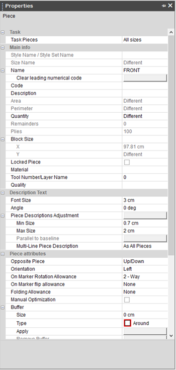
-
View the information in the pane as follows:
Field
Description
Task
Task Pieces
Allows you to change the scope for the pane. Following options are allowed:
-
Selected piece: This option is selected by default when the piece properties are displayed by the Info command. With this option, defined attributes are applied to all instances of the current size of the selected piece.
-
All sizes: This option is selected by default when the piece properties are displayed by the All Sizes Info command. This option allows you to apply defined attributes to all instances of all sizes of the current piece.
-
Global: This option is selected by default when the piece properties are displayed by the Global Info command. This option allows you to apply defined attributes globally, i.e. to all instances belonging to all sizes of all pieces in the Marker file.
Main Info
Style Name/Style Set Name
Displays the Style Name or (if a Style Set was defined) Style Set Name.
This attribute is displayed for information purposes only and cannot be changed.
Size Name
Displays the size name of the pieces.
This attribute is displayed for information purposes only and cannot be changed
Name
Displays the piece name.
This attribute can be modified for the entire piece (all sizes) only; therefore the attribute cannot be changed if the Selected Piece or Global option is set in Task Pieces.
Clear leading numerical code
This option allows you to clear leading numbers from the Name field. For example, if the Name is 123ABC1234, the Clear Leading Numerical Code command trims three numbers from the beginning of the name, so the resulted name will be ABC1234.
This command cannot be applicable for certain piece instances; it affects all sizes of the certain piece, therefore the command does not appear when Selected Piece option is set for the Task Pieces.
Code
Displays an alphanumeric piece code.
This attribute cannot be set for certain piece instances; it affects all sizes of the certain piece; therefore the attribute cannot be changed when Selected Piece option is set for the Task Pieces.
Description
Allows you to set the piece description which can be shown in the printed Info report or placed on a piece in the graphics area.
This attribute cannot be set for certain piece instances; it affects all sizes of the certain piece; therefore the attribute cannot be changed when Selected Piece option is set for the Task Pieces.
Area/Perimeter
Displays the piece's area and perimeter.
This attribute is displayed for information purposes only and cannot be changed
Quantity
This attribute allows you to set ordered quantity of pieces. The defined value is used as the initial counter of pieces quantity in the Sizes List. Once pieces are nested, the counter in the size list will be decreased providing you with the amount of remained pieces to be nested.
When the pane is displayed for the selected piece size (Selected Piece option is selected in the Task Pieces field), the specified value will be applied for the selected size only. When the All Sizes option is chosen in the Task Pieces, the defined value is applied to every size of the current piece. In a case when the Global option is chosen in the Task Pieces, the specified value is applied to each size of every piece within the Marker file.
Remainders
Displays the number of extra pieces that will be naturally cut in a case when the ordered quantity of pieces is not divisible by number of plies. For example if 30 pieces are ordered with 6 plies, 5 instances of the piece should be placed on the Marker resulted in exact cutting of quantity required by order. In such a way, the value of 0 will be displayed for Remainders. However, if 7 plies are used for the same amount of pieces, placing of 5 pieces on the Marker results in cutting of 5 extra pieces. In this case, the value of 5 will be displayed for Remainders.
This attribute is displayed for information purposes only and cannot be changed.
Plies
Displays the number of plies, as they were set in the Marker Definitions dialog.
This attribute is displayed for information purposes only and cannot be changed.
Block Size
X/Y
Displays the size of the box surrounding the piece, i.e. maximum horizontal (X) and vertical (Y) dimensions of the piece.
These attributes are displayed for information purposes only and cannot be changed.
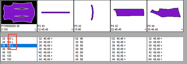
Locked Piece
This option allows you to avoid piece placement by Automatic Nesting. However, this option does not prevent manual placement of pieces.
When the Selected Piece option is chosen in the Task Pieces, locking is applied to the current size of the selected piece only. When the All Sizes option is chosen in the Task Pieces, locking is applied to all sizes of the certain piece. When the Global option is chosen in the Task Pieces, locking affects all pieces, i.e. none of the pieces will be placed automatically.
When this option is activated for pieces / sizes, corresponding sizes are marked with the L letter in the sizes table.
Material
This attribute allows you to define the Material of the piece. Material could be defined either by typing or by choosing from the list of materials available in the Marker application.
This attribute cannot be set for certain piece instances; it affects entire piece (all sizes); therefore, the attribute cannot be changed when Selected Piece option is set for the Task Pieces.
Tool Number/Layer Name
This attribute allows you to define the Tool/Layer associated with the piece. Tool/Layer could be defined either by typing or by choosing from the list of tools/layers available in the Marker application.
This attribute cannot be set for certain piece instances; it affects entire piece (all sizes); therefore, the attribute cannot be changed when Selected Piece option is set for the Task Pieces.
Quality
This attribute allows you to define the Quality associated with the piece. Quality could be defined either by typing or by choosing from the list of Quality types available in the Marker application.
This attribute cannot be set for certain piece instances; it affects entire piece (all sizes); therefore, the attribute cannot be changed when Selected Piece option is set for Task Pieces.
Description Text
Font Size
This attribute allows you to define the size of the font used for the piece description which is displayed/plotted on the piece.
The display and plot of the description is controlled via the Piece Display Attributes dialog.
Angle
This attribute allows you to define the orientation of the description text. The orientation is defined by an angle measured from the positive direction of the X axis.
Piece Descriptions Adjustment
This command allows you to automatically adjust the piece description as follows: the description text size is automatically set to be equal to the Max Size value; and the Angle is set to 0.
Min Size/Max Size
These attributes allow you to define minimal and maximal size of text used for the piece description. If actual text size for the description exceeds these limits, the description will appear using the closest text size limit value.
Parallel to Baseline
This command allows you to set the piece description direction to be parallel to the baseline, i.e. the Angle value should be set to 0.
If the Angle value is set to 0, this command is disabled.
Multi Line Piece Description
This attribute allows you to define the display style of the piece description. The following options available:
-
As All Pieces: Displays the description on the piece not taking lines into account.
-
One Line Form: Displays the description in a single.
-
Multi Line Form: Displays the description in multiple lines.
Piece Attributes
If the Pair option is used for the piece in the PDS, the Opposite Piece option allows you to define the direction of the opposite piece mirroring. The following options are available in the drop-down list:
-
None: The opposite piece is not available.
-
Up/Down: The opposite piece is obtained by vertically mirroring the piece's geometry
-
Left/Right: The opposite piece is obtained by horizontally mirroring the piece's geometry
This attribute cannot be set for certain piece instances; it affects entire piece (all sizes); therefore, the attribute cannot be changed when Selected Piece option is set for the Task Pieces.
Orientation
This attribute allows you to define the piece orientation which is displayed within the piece description next to the bundle number. The following options are available:
-
None: Piece orientation is not available.
-
Left: The left orientation is set to the piece. The L letter appears within the description. When the Left orientation is chosen, the orientation of the opposite piece is automatically set to be Right.
-
Right: The right orientation is set to the piece. The R letter appears within the description. When the Right orientation is chosen, the orientation of the opposite piece is automatically set to be Left.
This attribute cannot be set for certain piece instances; it affects entire piece (all sizes); therefore, the attribute cannot be changed when Selected Piece option is set for the Task Pieces.
This option defines the piece rotation allowed for the certain piece during the placement. Following options are available:
-
1-way: In this case rotation is not allowed; pieces can be placed only in base orientation with no rotation.
-
2-way: In this case 180 degrees rotation only is allowed, i.e. pieces can be placed either in base orientation or rotated by 180 degrees.
-
4-way: In this case incremental 90 degrees rotation only is allowed, i.e. pieces could be placed either in base orientation or incrementally rotated by 90 degrees relative to base orientation.
-
8-way: In this case only incremental 45 degrees rotation is allowed, i.e. pieces can be placed either in base orientation or incrementally rotated by 45 degrees relative to base orientation.
-
Any: In this case rotation is allowed for any angle.
This attribute cannot be set for certain piece instances; it affects entire piece (all sizes); therefore, the attribute cannot be changed when Selected Piece option is set for the Task Pieces.
On Marker Flip Allowance
This option allows you to flip pieces on the Marker table in order to achieve better material utilization. The following options are available:
-
None: In this case flipping of piece is not allowed; pieces can be placed only in base orientation with no flipping.
-
Flip X: In this case flipping of piece on the X axis is allowed. When this option is chosen, the piece is marked by the M letter in the sizes table.
-
Flip Y: In this case flipping of piece on the Y axis is allowed. When this option is chosen, the piece is marked by the M letter in the sizes table.
This attribute cannot be set for certain piece instances; it affects entire piece (all sizes); therefore, the attribute cannot be changed when Selected Piece option is set for the Task Pieces.
Folding Allowance
Marker allows you to place the material on a table in a number of connected plies. A number of plies and their connection are defined in the Marker Definitions dialog. The plies connection could be performed on top/bottom edge, on left/right edge or on both. When material is arranged in a number of connected plies, pieces could be placed in folded state on the material edge.
The folding allowance option enables you to allow to place pieces at material edge with folding. Once the folding is allowed, folded pieces placement could be performed either automatically, by automatic nesting or manually using the Placement Tools toolbar. Following options are available:
-
None: In this case folding is not allowed for the piece.
-
Up/Down: In this case, a piece could be folded in vertical direction and placed at the top/bottom material edge. Such a placement could be performed when Layout Mode (in the Marker Definitions dialog box) is set to Tubular or Folded.
-
Left/Right: In this case, a piece could be folded in horizontal direction and placed at the left/right material edge. Such a placement could be performed when Layout Mode (in the Marker Definitions dialog box) is set to Faced or Folded.
-
All: In this case, a piece could be folded in both horizontal / vertical directions and placed at all material edges. Such a placement could be performed when Layout Mode (in the Marker Definitions dialog box) is set to Folded.
Manual Optimization
This option allows you to preserve the current cutting order, and exclude selected pieces from consideration when shared lines auto-detection, start points and cut direction optimization procedures are performed using the Cut/Plot Optimization dialog.
This option cannot be set for certain piece instances; it affects entire piece (all sizes); therefore, the attribute cannot be changed when Selected Piece option is set for the Task Pieces.
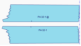
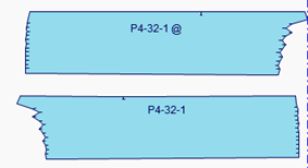
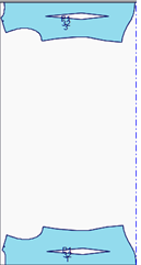
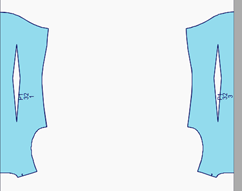
Buffer
This group provides you with the possibility to apply buffer to selected pieces. A buffer creates an offset distance from the piece geometry or its parts which is used to keep a gap between pieces to achieve easier cutting of the Marker.
When the buffer type and size are defined as described below, the buffer is calculated resulting in the creation of buffer geometry around either entire piece or its area. Applying of multiple buffers to a single piece is allowed. In a case when a new buffer is applied to a piece geometry where the buffer was previously defined, the existing buffer geometry is modified accordingly.
Size
Sets the size of the buffer. The size is the absolute value of the buffer (i.e. it doesn't add to any existing buffer).
Type
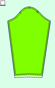
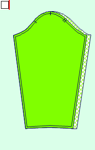
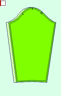
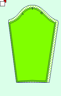
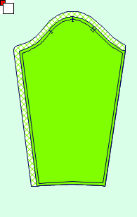
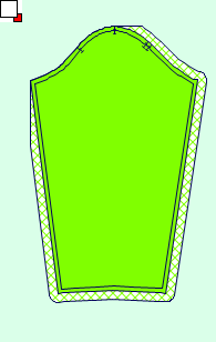
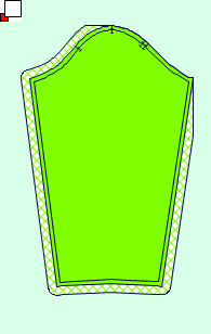
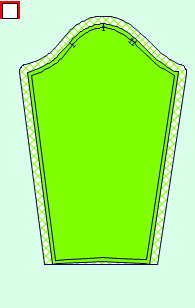
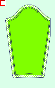
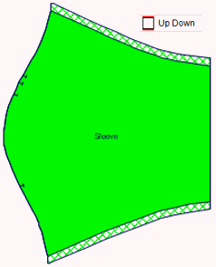
Sets the type of the buffer. In the following figure the icon are showing on the top left of every figure.
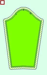
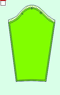
Original piece
Around
Top
Bottom
Right
Left

Convex
Up Right
Up Left
Down Right
Down Left
Up Left Right


Down Left Right
Right Up Down
Left Up Down
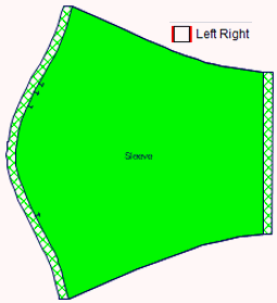
Left Right
Up Down
Apply
This button allows you to apply the buffer to the selected piece geometry according to the Size and Type defined.
In case the piece geometry contains self-intersections, the warning message will be displayed.
Remove Buffer
This button enables you to clear the buffer from the current piece and reset the piece geometry to the original contour.
Scale/Shrink by Factor
This group allows you to scale selected pieces. It is allowed to perform uniform / non-uniform scaling of piece by defining scale factors in both X and Y directions.
Scaling could be performed either using percentage or ratio depending on the Use Percent Values in Scale option available in Preferences.
When the percentage is used for the scale value definition, the value of 0 describes the initial piece scale; positive value increases the scale, negative value decreases the scale respectively.
When working with ratio, the value of 1 describes the initial piece scale; values above 1 increase the scale, values below 1 decrease the scale respectively.
X and Y values are enabled for every Task Pieces option.
When the Selected Pieces option is set for the Task Pieces, the Scale/Shrink By Factor button appears in the group header row. This button displays the Scale/Shrink by Factor dialog which provides you with an advanced definition of scaling.
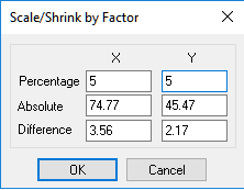
For every axis, the dialog box provides you with the possibility to define scaling by one of following values:
-
Percentage: This field enables you to define scaling as a percentage of the initial size. The value of 0 describes the initial piece scale; positive value increases the scale; negative value decreases the scale respectively.
-
Absolute: This field enables you to specify the absolute size of the scaled piece. By default, the initial size of the piece is displayed.
-
Difference: This field enables you to specify the size difference which should be applied to the scaled piece. By default, the field is empty.
Adjustment of one value causes automatic recalculation of other values. E.g. when the absolute size of a piece is equal to 200, the modification of this value to 180 will cause the automatic update of Percentage value to be -10%; the difference will be set to -20.
X
Y
Tilt
This group allows you to define tilt for selected pieces. By tilt is meant an angular tolerance which is applicable when the piece is placed in certain orientation by automatic nesting. In other words, the tilt parameter describes allowed angular deviation from the piece default orientation (defined by On Marker Rotation Allowance) which could be used for optimal piece placement when an automatic nesting is performed.
.
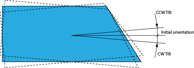
The tilt value can be set in the Tilt group header row as well. In this case, the specified value is applied to both CW and CCW Tilt and vice versa. When both CW and CCW Tilt values are equal, the common angular tolerance value is displayed for the Tilt group header. When CW and CCW Tilt values are different, the value for the Tilt group header is empty.
This attribute cannot be set for certain piece instances; it affects entire piece (all sizes); therefore, the attribute cannot be changed when Selected Piece option is set for the Task Pieces.
CW Tilt
Enables you to define the angular tolerance in clockwise direction
CCW Tilt
Enables you to define the angular tolerance in counterclockwise direction
Report
Piece Report
This section allows you to generate a report for the selected piece of the current size. The report contains a summary of piece information, such as notches amount, cutting length etc.
Save to File
This option allows you to save the piece report in a text file.
Print
This option allows you to print the piece report using the default printer.
Size Report
This section allows you to generate a report for the all sizes of the currently selected piece. The report contains a summary of piece information, such as piece area, perimeter etc.
Print
This option allows you to print the size report using the default printer.
Piece Placement
This group provides you with the parameters of the piece placement.
Task Instances
This parameter allows you to define the scope of piece instances for which placement properties are displayed. The availability of the entire Piece Placement group depends on the Task Instances option, as well as selection performed in the graphics area / sizes list.
The following options are available:
-
Selected instances: When this option is chosen, the Piece Placement group provides you with the placement parameters for a piece instance currently selected in the graphics area. If none of the piece instances are selected, the Piece Placement group is not displayed.
-
All instances: When this option is chosen, the Piece Placement group provides you with the placement parameters common for all piece instances currently placed on the Marker table.
Placement on Marker
This group provides you with the position and orientation of the current piece instance on the Marker table and allows you to adjust it.
The piece position is defined by X and Y coordinates measured from the Marker table origin (0,0) which is located at the bottom left corner of the Marker table displayed in the graphics area.
X
The position of the piece along the X axis can be defined by specifying left most/right most coordinate of the piece or by specifying the piece center coordinate.
Left/Center/Right
Left, Right and Center parameters available for the X coordinate definition are interrelated, i.e. update of one parameter causes automatic recalculation of others.
Y
The position of the piece along the Y axis can be defined by specifying upper/lowest coordinate of the piece, or by specifying the piece center coordinate
Top/Center/Bottom
Top, Bottom and Center parameters available for the Y coordinate definition are interrelated, i.e. update of one parameter causes automatic recalculation of others.
Rotation
This parameter provides you with the actual rotation of the selected piece instance.
Flipped
This parameter provides you with the actual flip status of the selected piece instance.
Parameters
Legal Intersection
This option allows you to control intersection for the selected piece. When the option is activated, intersection of the current piece with other pieces is allowed; Marker will not highlight intersected pieces.
When the option is inactive, the intersection of the current piece with other pieces is not allowed; Marker will highlight intersected pieces.
Stop before cutting (opstop) this piece
This option allows you to output the Opstop command before cutting the current piece instance. This option can also be controlled by the Ctrl + Alt + W shortcut.
Don't cut the piece
This option allows you to exclude the current piece instance from the cut/plot output. When the option is activated, the current piece instance will not be cut/plot.
Flaw on the Marker
This option allows you to define the selected piece instance as a flaw on the Marker. The material area defined by a piece instance marked as flaw will be avoided during the automatic nesting.
Label
This parameter enables you to specify the label applied to the selected piece instance only. The defined label will be plotted together with the piece.
-