Optitex Viewer
The Optitex Viewer is a standalone utility that allows you to view PDS
and MRK files without the need for an Optitex license. With the Optitex
Viewer you can view all pieces in the file one at a time, view piece properties,
including names, points, stitches, fill color, etc. as well as print,
plot, and arrange for plot.
The viewer consist of two splitter windows that “remember” the sizes
and positions in all parent applications.
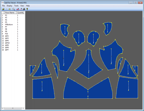
PDS file opened with Optitex Viewer
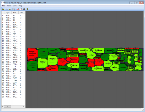
MRK file opened with Optitex Viewer.
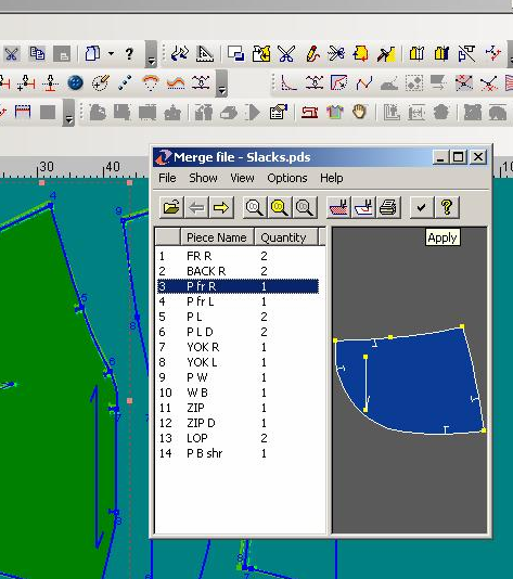
How it works embedded in PDS
-
Click File
> Merge Style File…
-
The Merge File
dialog appears.
-
Choose one ore more pieces and click Apply.
The merge mechanism should then run.
-
The viewer has ability to drag and drop one
or more pieces from the preview window, or from the list of pieces
to run the merge.
How it works embedded in PDS
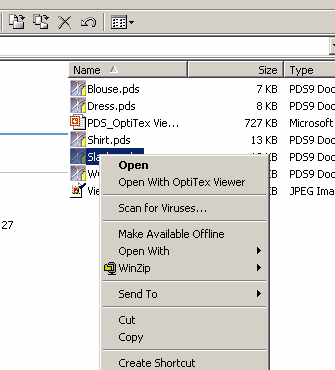
How it works in Windows shell
-
Click RBM on the PDS file. “Open with Optitex
Viewer” appears.
-
Click it to run the Viewer.
How it works in Windows shell
Current capabilities:
-
Additional tools available for printing, plotting,
arrange to plot operations.
-
Enabled to change such show properties of the
Wiewer as viewing the names, points, stitches, fill color and so on.
-
You can open any new PDS file within the Viewer
and from Windows Explorer.
-
Able to run between the files in the current
folder within the Viewer.
-
Ability to open Marker files and view the window
of sizes in the current file.
Optitex Viewer Menu Features
You can use the  Tolerance
Check Tool to verify if a cut piece's size is within
a certain tolerance.
Tolerance
Check Tool to verify if a cut piece's size is within
a certain tolerance.
The Tolerance Check tool
enables you to verify if a cut piece's size is within a certain tolerance.
You can perform this verification by placing a cut piece onto a large-size
monitor, displaying the actual piece geometry in real size.
With Tolerance Check, you can also:
-
Define the tolerance for the geometry of
an actual piece.
-
Have control over the display of the geometry
corresponding to the upper and lower limits of the tolerance field.
-
Separately control the display of tolerance
boundaries for external and internal cut contours, as well as
for notches.
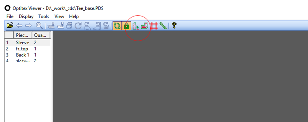
To use the Tolerance Check tool:
In the Optitex Viewer, click the Tolerance
Check button  on
the toolbar.
on
the toolbar.
Note:
This button is enabled when the Validation Mode is activated and a
single piece is selected in the Piece List; otherwise the button is
disabled.
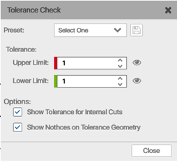
The Tolerance Check dialog
box appears. Using the options here, you can control the display of
the geometry representing the upper and lower limits of the tolerance
field.
Preset enables you to define
and activate preset options used through this dialog box. The preset
is composed of all parameters and options available within the dialog
box, including:
-
Upper/Lower tolerance limit values.
-
Visibility rate for Upper/Lower limit geometry.
-
The state of the Show Tolerance for Internal
Cuts option.
-
The state of the Show Notches on Tolerance
Geometry option.
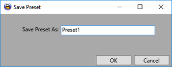
These options form a preset that can be stored and then loaded back
into the dialog box. The Save
button  allows you to choose and activate a preset
from the list, and save the current set of data appearing within the
Tolerance Check dialog box as a new preset. Once you click Save, the
Save Preset dialog box appears,
which enables you to specify the name of the preset.
allows you to choose and activate a preset
from the list, and save the current set of data appearing within the
Tolerance Check dialog box as a new preset. Once you click Save, the
Save Preset dialog box appears,
which enables you to specify the name of the preset.
The Tolerance section enables
you to define the upper and lower tolerance limits, as well as control
the visibility of the corresponding geometry. Once a certain limit
is specified, the tolerance limit geometry is created by offsetting
the initial nominal piece geometry. When the offset geometry is created,
it is displayed. A positive tolerance value generally increases the
pieces area, whereas a negative value contracts the piece. When a
zero value is specified, the offset is not calculated.
The visibility toggle buttons  allow you to
control the visibility of the corresponding tolerance limit geometry.
When a visibility toggle button is turned off, the corresponding tolerance
limit geometry does not appear in the graphics area.
allow you to
control the visibility of the corresponding tolerance limit geometry.
When a visibility toggle button is turned off, the corresponding tolerance
limit geometry does not appear in the graphics area.
Show Tolerance for Internal Cuts
gives you advanced control over the visibility of tolerance geometry
for internal cuts. When this option is selected, the tolerance limit
geometry is calculated and displayed for internal cuts as well. When
this option is not selected, internal cuts are skipped during the
tolerance limit geometry calculation and display.
Note:This
option does not control the visibility of internal cuts in the nominal
piece geometry. The display of internal cuts on the nominal geometry
is controlled normally via Display Attributes.
Show
Notches on Tolerance Geometry gives you advanced control over
the display of notches on the tolerance geometry. When this option
is selected, notches are displayed on the tolerance limit geometry.
When this option is not selected, notches are not displayed on the
tolerance limit geometry.
Note:This
option does not control the visibility of notches in the nominal piece
geometry. The display of notches on the nominal geometry is controlled
normally via Display Attributes.
Notes that when this option is
selected, notches are displayed on tolerance limit geometry at an
automatically calculated position. Once a notch is transposed from
the nominal geometry to tolerance limit geometry, it is placed on
the same segment, preserving the same proportion of distances between
the notch and the two neighboring geometry vertices (located before
and after the notch).
Additional
options within Validation Mode let you validate cut
pieces against piece geometry displayed in real scale on a 4k screen.
With Validation Mode, you
can validate cut pieces against piece geometry displayed in real scale
on a 4k screen. This helps enhance quality control efficiency, and
reduces the need for cardboard, paper, or plastic patterns - saving
on time, cost, and storage.
Validation Mode is viewable from the Pattern
Validation toolbar and the View
menu. It utilizes the existing single piece focus of Optitex Viewer
when viewing a PDS file.
The following options are available in Validation Mode:
-
Pan tool
- moves the piece on the canvas.
-
Free rotation
- handles on the corners of the bounding box will allow you to
rotate freely around the bounding box diagonal crossing.
-
Rotate
90° clockwise
-
Rotate
90° counter-clockwise
-
Rotate 180°
-
Enter Validation
Mode - will be entered only when there is a single piece
on the canvas. The button zooms the view to 1:1 mode, positioning
the piece in the center of the screen.
-
Lock (zoom
and pan are locked) - This will automatically be on when
you enter Validation Mode. If you disable the lock, you can then
pan and move the piece. Note that you cannot change the zoom factor
while in Validation Mode.
-
Set Scale
- Allows you to scale the piece up to the allowed tolerance. For
example, selecting 1 on the X axis will scale the piece in the
percentage equivalent to 1 cm/PieceWidth. Maintain
Aspect Ratio ensures that the X/Y scaling maintains the
aspect ratio. Show Nominal Path
presents the original piece contour when checked; otherwise, only
the scaled version is presented. Show
Max and Show Min
display the maximum and minimum scaling, respectively, on the
X and Y axis.
-
Offset
Grid Tool - When clicking this, the top most, bottom most,
right most, left most points and a grid of reference lines will
be presented. The horizontal/vertical grid lines will be trimmed
by a predefined length parameter in the INI file, and if they
intersect. See the Optitex
Viewer INI Settings file for more information on the various
grid definitions.
-
Ruler
- Presents a visual ruler on the screen. When the ruler is selected,
the rotate and pan tools will move/rotate the ruler and not the
piece. Ruler coordinates are in skips of 0.5 mm from 0 to 20 mm.
The ruler can be toggled on only in Validation Mode.
Additional information on these options can be found in the Optitex
Viewer INI Settings file - including editable fields, color and
grid definitions, and configurations.