Setting Up a Digitizer
Connecting the Digitizer
1. Connect cable from the digitizer to the back of your computer.
Digitizers use two kinds of cable to connect to computers; Serial Cable (RS232) and USB cable. Note which one you are using.
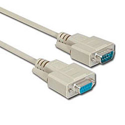
Serial Cable
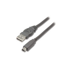
USB Cable
Digitizer Settings
-
Open Optitex PDS and go to File > Digitizer > Digitizer Settings.
-
The Digitizer Settings window will appear:

-
File>Digitizer>Digitizer Settings
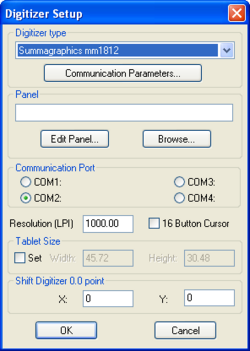
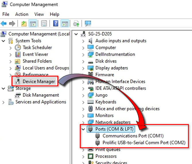
 Note: Com Port setting must match the actual com port to which the digitizer is connected.
Check the Windows Device Manager to see the correct com port.
For example:
Digitizer Settings
-
Check to Make sure that your Digitizer Type and Communication Parameters are set correctly for your type of digitizer.
-
CheckOptitex Supported Digitizers for a full listing of digitizers and their appropriate settings.
Digitizer Window Overview

-
Location:
-
Menu
-
File>Digitizer>Digitize
-
-
Toolbar
-
General
-
-
Toolbox
-
Windows Tools
-
Icon:

To Set Up Digitizer:
The Digitize Window is divided into sections to separate its functions, and contains buttons for additional functions.
-
The Menu Section contains each of the functions that a digitizer is capable of using these buttons can be used for understanding the use of each function without the use of the digitizer. These functions define a type of object that can be placed within a digitized piece, and using the mouse, you can click on a function, and click anywhere on the blank space to the left to test the function.
The meaning of each of these options are as follows:
|
Button |
Function |
|---|---|
|
Point |
Creates a graded, non-curve point along a contour |
|
Grade |
Marks the nested locations of a graded point |
|
Notch |
Creates a notch on an external contour |
|
Dir.Notch |
Creates a directional notch on an external contour |
|
Button |
Creates a button or drillhole on the inside of a closed piece |
|
Line |
Creates a two-point internal line segment |
|
Circle |
Creates a circle using center location and radius |
|
Grd/Crv |
Creates a graded curve point |
|
nGrd/nCrv |
Creates a non-graded, non-curve point |
|
Dart |
Marks the first leg, second leg, and tip of a dart |
|
Contour |
Begins a complex internal contour within a closed piece |
|
Baseline |
Marks the baseline of a piece |
-
The Digitizer Status Button opens a window that will display the current staus of the digitizer, as well as the default modes for types of internals.
-
The Internal Commands Button opens a window where you can set the default settings for internals that are created using the digitizer.
-
The Piece Information Button allows you to modify the piece information for the current piece you are working on. You can change the piece information one by one as you digitize, or more easily - fix them from within the PDS workspace.
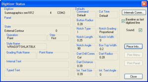
1. Digitizer status Window

2. Internal Commands Window
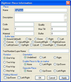
3. Piece Information Window
Testing Digitizer Calibration
-
Take an 8.5x11" sheet of paper and tape it to your digitizer board.
-
Digitize around the perimeter of the piece using only four grading, non-curve points total(You can use the crosshairs on the digitzer puck to be as accurate as possible while digitizing).
-
Click '"Done"' to send the piece to the workspace.
-
Find the Piece, and bring it to the workspace.
-
Press F8 to see the length of each contour between grading points.
Note: The human hand will never be able to perfectly recreate the exact size
and shape of any contour digitzed in. Your measurements can be as far
as .1 or even .2" off depending on the size of your pattern.
 See also: Optitex Supported Digitizers