Internal Contour To Lines
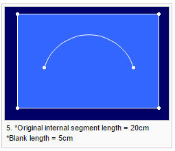
Use the Internal Contour to Lines command to divide a selected internal contour into equal lines, according to the number of lines, line length and blank length.
To add internal contour to lines:
-
Select an internal contour.
-
Invoke the Internal Contour To Lines command. The Convert Internal Contour To Lines dialog is displayed.
-
Enter the required values.
-
Click OK.
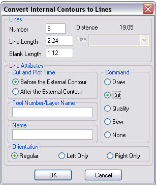
View the fields as follows:
|
Field |
Description |
|
Number |
Sets the number of lines to be created. In this example:
|
|
Line Length |
Sets the length of each line.
|
|
Black Length |
Sets the length of the gap between each line. The length is calculated along the selected segment.
|
|
Distance |
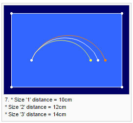
Indicates the length of the selected segment. When you change the selected size, the value displayed in the Size combo box may change accordingly.
|
|
Size |
Enables you to select the desired size, if the piece has several sizes. The distances applied to the selected size will influence the other sizes. |
|
Cut And Plot Time |
Determines the cutting time attribute for the internal lines created, before or after the external contour is cut. |
|
Tool Number/ Layer Name |
Sets the Tool/ Layer. Layers are used when importing or exporting a file to other standard CAD file systems. |
|
Name |
Gives a name to the internal lines. |
|
Command |
Defines the tool that will be used on the lines when the file is sent to a cutter or plotter machine, such as Draw for a pen, Cut for a knife, etc. |
|
Orientation |
Determines the position of the internal contour - on the left piece only/ right piece only/ or on both pieces (if the piece is set as a pair). |