Gusset Tool
You can use the Gusset tool when you want to create a side panel (gusset) for a bag, backpack, pockets, etc. This allows you to create the gusset according to selected contours (front and back). A preview of the gusset is available while you are using the tool and allows you to see both a 3D and unfolded view of the final gusset. All options in the Gusset Tool dialog are updated dynamically once you change one of the parameters within the dialog. You will be able to see the final 3D and unfolded preview before you create the final piece.
Icon & Location
-

-
Menu: Tools > Gusset Tool
-
Toolbox: Build & Cut > Create Gusset
To use the Gusset tool:
1. Open
your pattern.
Make sure you have the two pieces for which you are creating the gusset.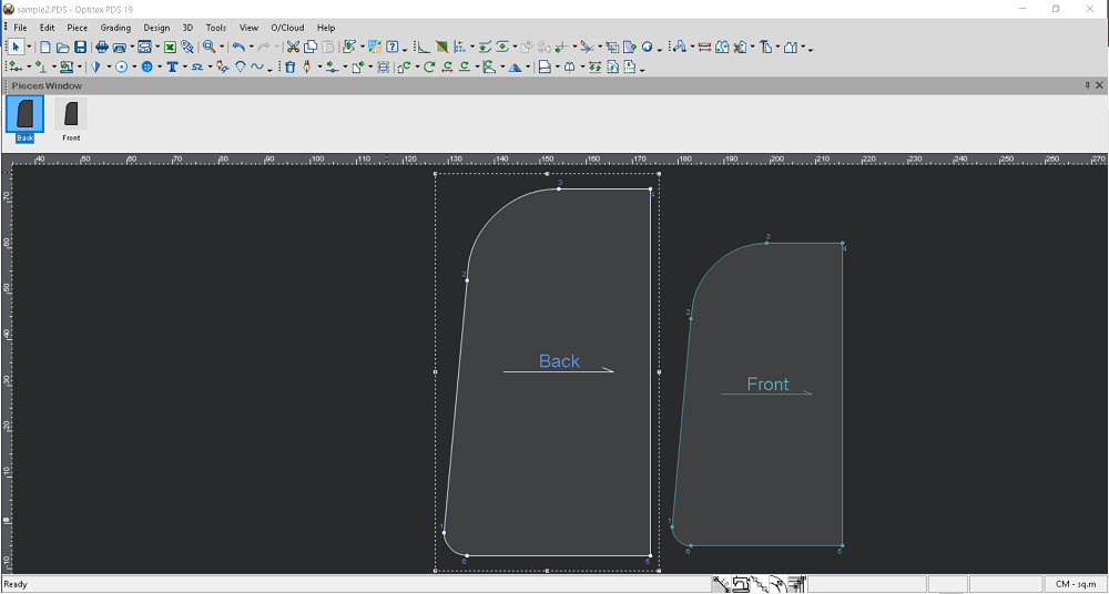
2. You
should first adjust the position of the back and front pieces manually,
so that you can determine the X/Y position where the pieces connect.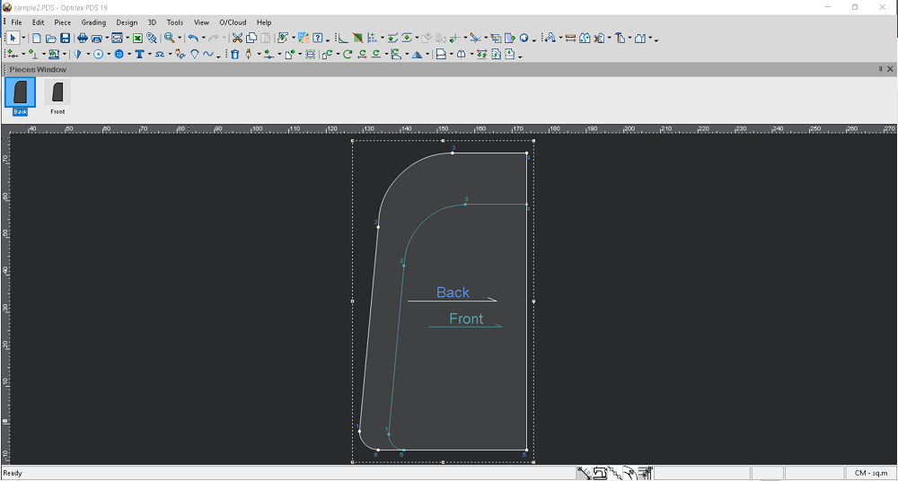
3. Go
to Tools > Gusset Tool.
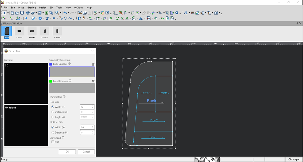
The Gusset Tool dialog appears: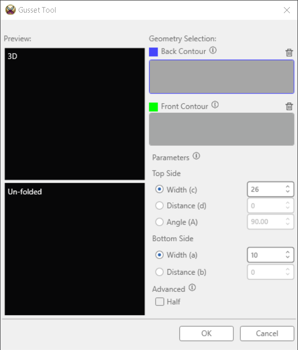
4. While keeping the Gusset Tool dialog open, you first need to select the contour on the back piece.
5. In
the Pieces Window select the Back
piece as follows: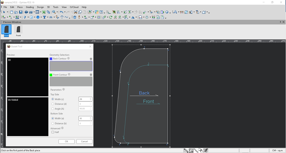
6. In
the Gusset Tool dialog, verify
that the Back Contour section
appears with a BLUEborder.
The mouse cursor changes into a selection cursor: 
7. To
select the contour, first
click on the first point (starting point). The selected point is
marked with an X. 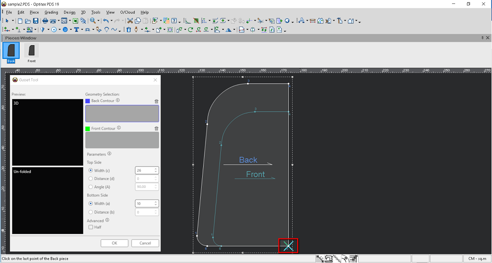
8. Next, click on the second point
(last point):
Once the contour is selected, it appears in BLUE
in the 3D preview. The piece name and the point numbers appear
in the Back Contour field as follows: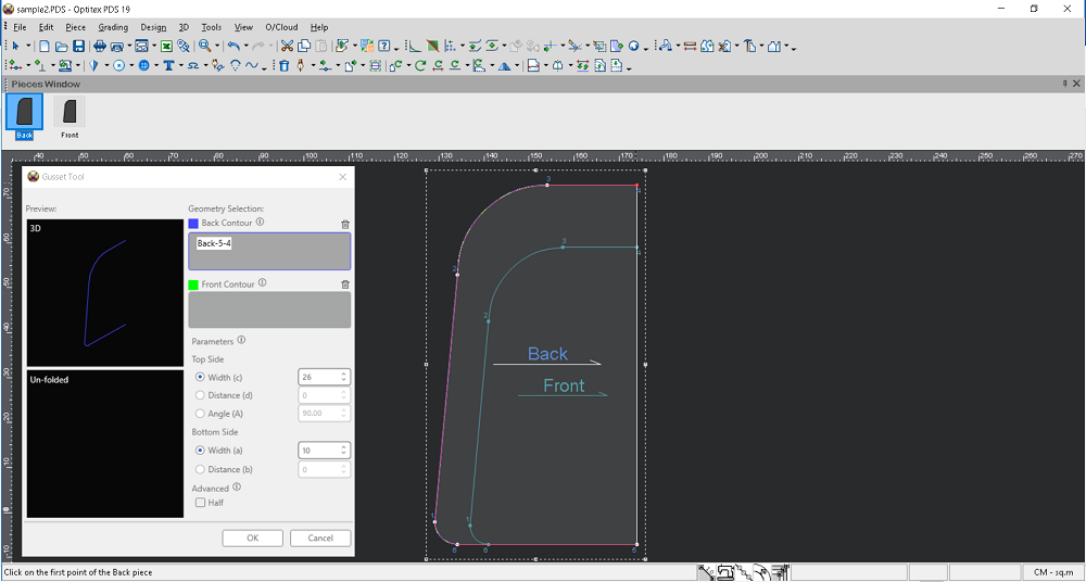
9. Next you need to select the contour on the front piece.
10. First click inside the Front Contour section, which will appear with a GREEN border.
11. In
the Pieces Window, select the
Front piece as follows:
12. To
select the contour, first
click on the first point (starting point) of the front piece: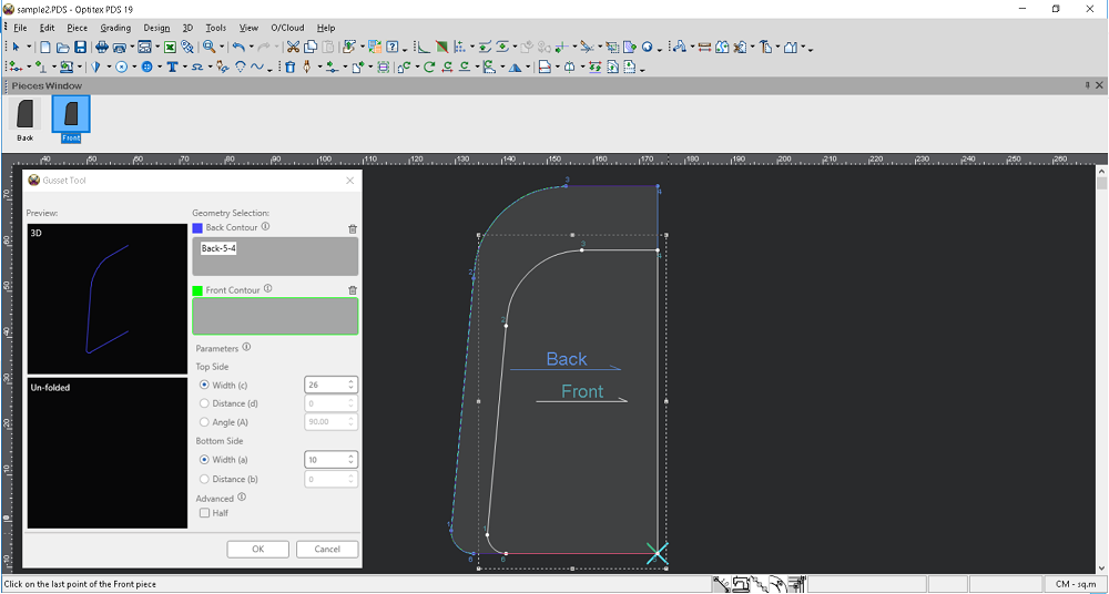
13. Next, click on the second point
(last point) of the front piece:
Once the contour is selected, it appears in GREEN
in the 3D preview and the Unfolded preview displays. The piece
name of the selected contour and the point numbers appear in the Front Contour field as follows: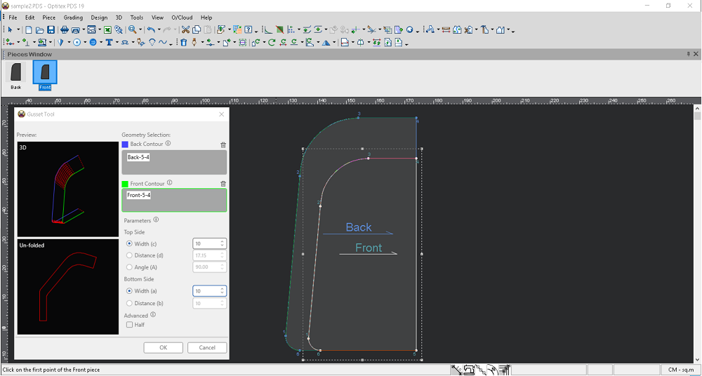
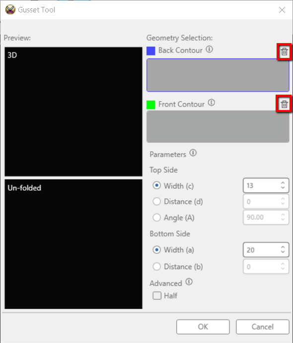
Note:
If you want to reselect a segment during the process, click the trash
icon (delete) icon, as shown below.
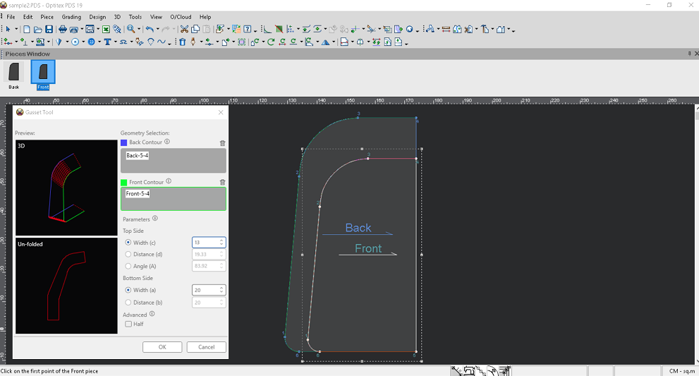
14. In
the Parameters area, you can enter
the desired parameters - width (c), distance (d), and angle (A) - for
the Top Side, and width (a) and
distance (b) for the Bottom Side.
Note:
When you want to control the width/distance/angle, select the radio button
and change the required parameter. Once you change one of the parameters,
the others for the Top Side will be dynamically recalculated. When you
want to control the width/distance for the Bottom Side, select the radio
button and change the required parameter. Once you change one of the parameters,
the other for the Bottom Side will be dynamically recalculated.
The scheme diagram below illustrates the parameter options.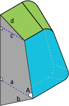
a (Bottom Width ) - is a distance between the first point of the back contour and the first point of the front contour, measured along the normal to the plane of the back contour.
b (Bottom Distance) - a is the shortest distance between the first point of the back contour and the first point of the front contour.
A (Angle) – is an angle between the plane of the front contour and normal of the plane of back contour.
c (Top Width) - is a distance between the last point of the back contour and the last point of the front contour, measured along the normal to the plane of the back contour.
d (Top Distance)- a is the shortest distance between the last point of the back contour and the last point of the front contour.
Note: The first and last contour points are determined according to the selection sequence.
The Preview updates accordingly:
15. If your back and front pieces are defined as half, in the Advanced area, the Half checkbox will be available, and you can select the option in order to create a gusset with a half piece definition. The Half option allows creating half gusset geometry when the back and front contours are defined as half as well. The symmetry line used for the half reflection is created through the last points of the front and back contours
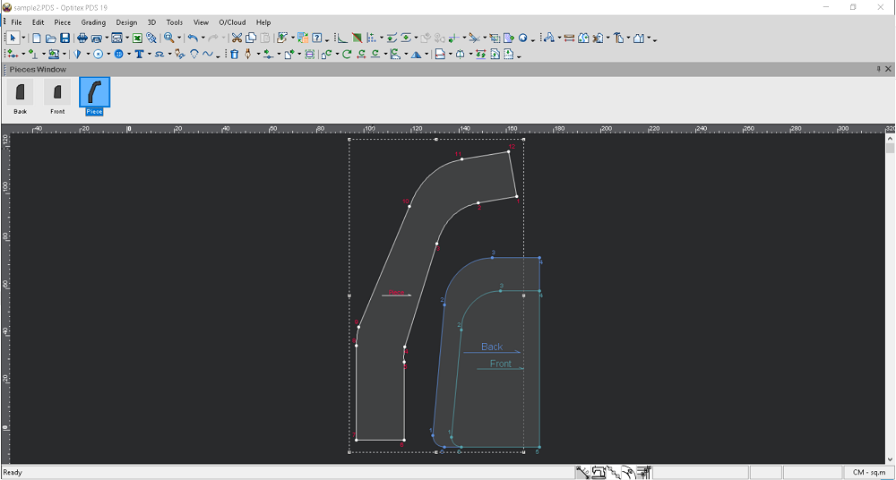
Click Ok.
The gusset is created as follows:
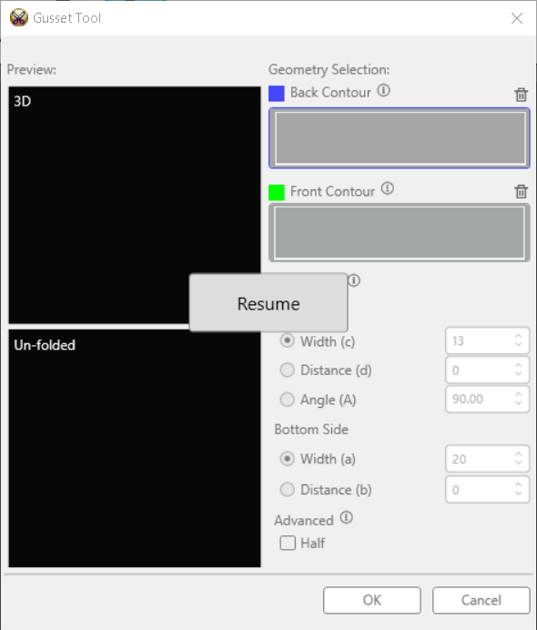
Note: When the Gusset Tool is activated and you select another tool; for example, Move Piece, a Resume button displays in the middle of the dialog. Clicking the Resume button allows you to continue using the tool.
Advanced Capabilities for Complex Geometry
The tool also allows you to create a gusset when your front and/or back panels contain multiple pieces.
Open your pattern. You should first adjust the position of the back and front pieces manually, so that you can determine the X/Y position where the pieces connect.
Go to Tools > Gusset Tool. While keeping the Gusset Tool dialog open, you first need to select the contour on the back piece. In the Pieces Window, select the Back piece. In the Gusset Tool dialog, verify that the Back Contour section appears with a BLUE border.
To select the contour, first click on the first point (starting point). The selected point is marked with an X. Next, click on the second point (last point). Once the contour is selected, it appears in BLUE in the 3D preview. Once you select the segment, the piece name of the selected segment and the point numbers appear in the Back Contour field as follows:

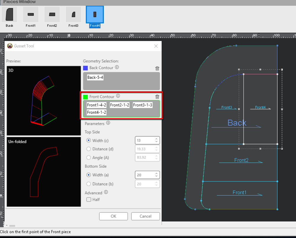
Next you need to select the contours on the front pieces. Select segments for each piece sequentially, in a clockwise direction. In this example, you would first select the bottom front piece (Front1), and select the first segment, and then continue with the others. Each selected segment will update the 3D and Unfolded previews accordingly.
Once each contour is selected, it appears in GREEN in the 3D preview and the Unfolded preview displays.
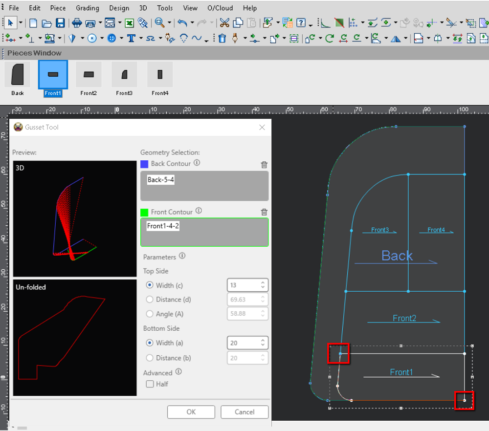
Select piece Front1 and select the first and last points:
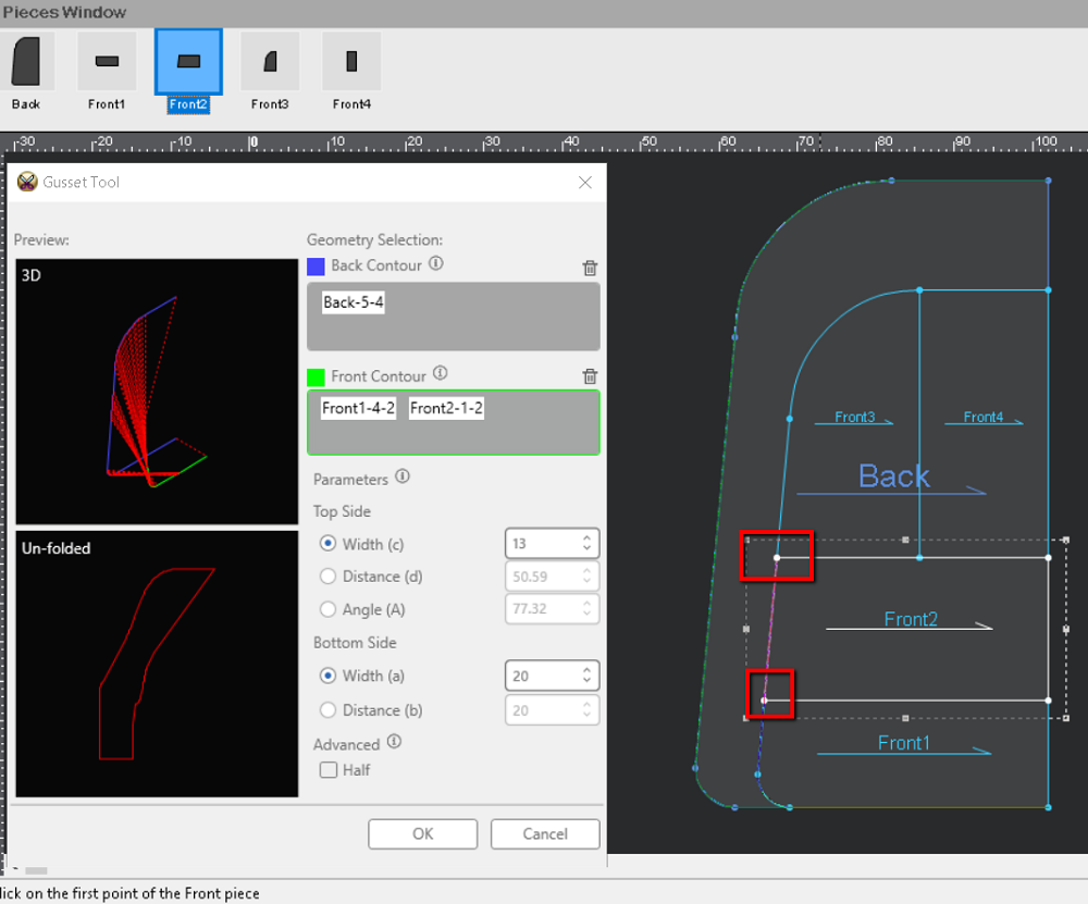
Select piece Front2 and select the first and last points:
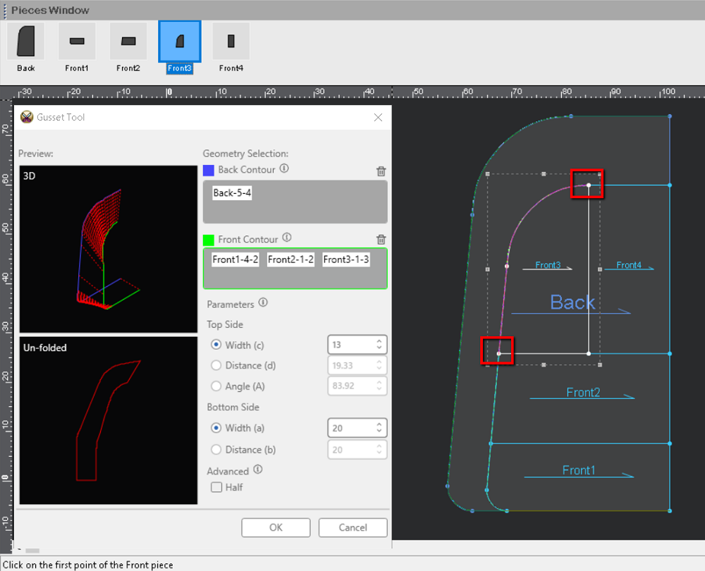
Select piece Front3 and select the first and last points:
Select piece Front4 and select the first and last points:
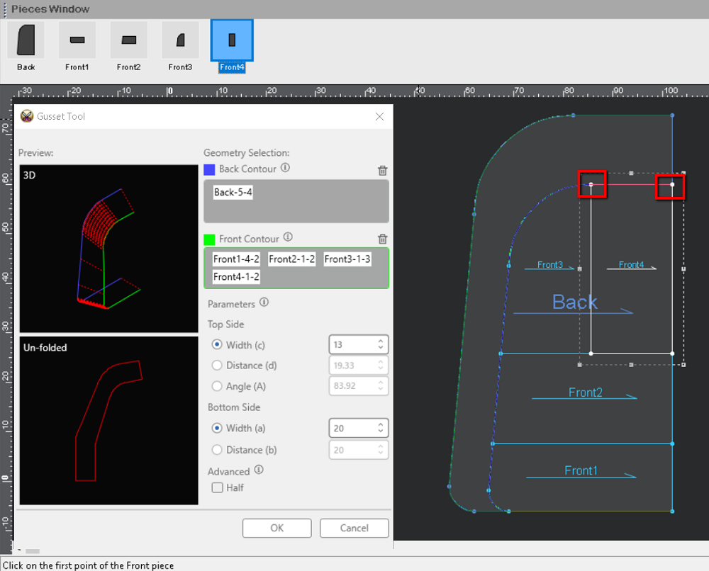
Note: If you want to reselect a segment during the process, click the trash icon (delete) icon, as shown below.
In the Parameters area, you can enter the desired parameters - width (c), distance (d), and angle (A) - for the Top Side, and width (a) and distance (b) for the Bottom Side.
Note: When you want to control the width/distance/angle, select the radio button and change the required parameter. Once you change one of the parameters, the others for the Top Side will be dynamically recalculated. When you want to control the width/distance for the Bottom Side, select the radio button and change the required parameter. Once you change one of the parameters, the other for the Bottom Side will be dynamically recalculated.
The Preview updates accordingly.
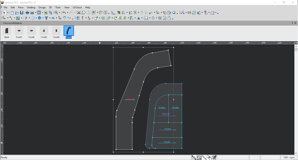
Click OK. The gusset is created as follows:
 See also:Getting to Know Optitex PDS 2D