Display Attributes
Controls the information that will be displayed on screen and in the output file.
Icon & Location
-

-
Menu: View> Pieces on Marker (F10)
Dialog Explanation
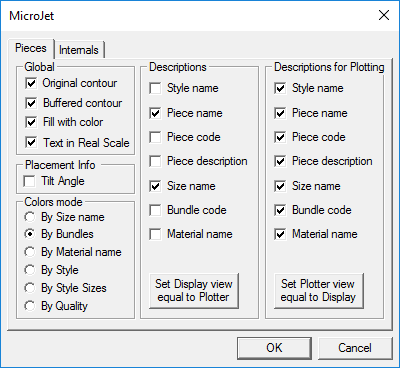
This dialog contains two tabs. The first tab controls the piece appearance and the second, the appearance of the internal elements in the file.
Pieces Tab
|
Field |
Description |
|
Global Section |
|
|
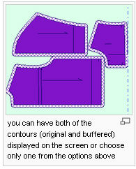
Original Contour |
Determines whether or not the original contour of a piece will be displayed. This option is used mainly when a piece contains a buffer, and you do not want the piece boundary displayed on the screen or with the output. |
|
Buffered Contour |
Determines whether or not the buffer will be visible on the screen. When a marker is sent to the plotter, it will be sent with the same attributes as those displayed on the screen. Therefore, if you want the buffer line displayed on the plotted paper, this option should be enabled.
|
|
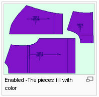
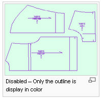
Fill with Color (Ctrl+F) |
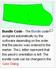
Fills the pieces with color according to a particular size or set (Bundle).The color can be changed via the Marker:Color Dialog from the Options menu. If there was no color assign, the default piece color will be used. Buffer will be displayed in the same color but with a different pattern
Note:Toggle the Color Fill on and off by pressing Ctrl+F. |
|
Text in Real Scale |
Determines how the Internal Text and Descriptions will be displayed on the screen. When enabled, the text and descriptions will display on the screen in the same scale as text will plot. When disabled, the text and descriptions will be displayed on the screen so that it is readable. |
|
Placement Info Section |
|
|
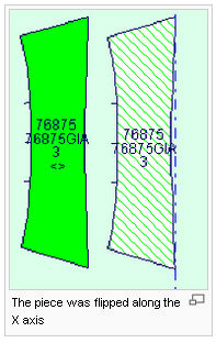
Tilt Angle |
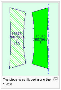
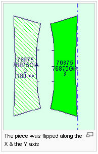
When the Tilt Angle option is enabled, the amount that each piece has been rotated or tilted will display on the tilted piece next to the piece Descriptions. Pieces that were flipped along the X axis will display brackets sign "< >" to indicate that the piece was flipped. Pieces that were flipped along the y axis will display "180" to indicate that the piece was flipped. Pieces that were flipped along both the X and the Y axis will display brackets sign "< >" along with 180 to indicate that the piece was flipped in two ways.
|
|
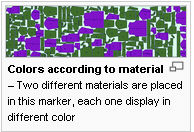
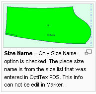
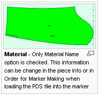
Colors Mode |
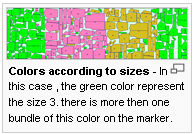
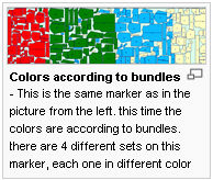
Select the color mode to be displayed. Choose between size name, bundles and material name. Selecting the Size Name option will color the pieces according to their sizes as they are defined in the PDS or in the Color Dialog. To view all the pieces that are in the same sets with the same color - select "By Bundle". In case you have pieces from different materials on your marker, have "By material" option selected to distinguish between the different material pieces.
|
|
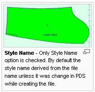
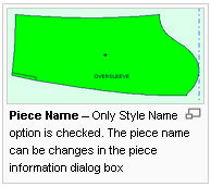
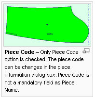
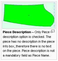
Pieces Description |
Select the checkboxes next to the piece description type to determine whether or not to display on the screen. Set display view equal to Plotter:Click on this button to copy the information from the left column to this section. This is way the description that displays will be the same as plotted.
|
|
Description for plotting |
Select the checkboxes next to the piece description type to determine whether or not to plot it out. Set plotter view equal to display: Click on this button to copy the information from the right side to this column. |
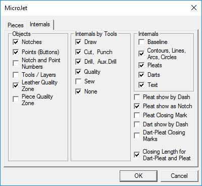
Internals Tab
|
Field |
Description |
|
Objects Section |
This section controls the internal objects display. Select the checkboxes next to the objects that you want to view on the screen and to plot out. |
|
Notches |
Determines whether or not the notches will be displayed on the piece and will be plotted. |
|
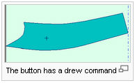
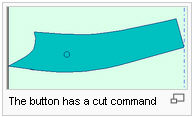
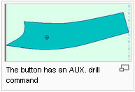
Points (Buttons) |
Determines whether or not drill holes will be displayed on the piece with output. Buttons with Cut attributes will plot as a circle approximately 3/8” in diameter. Those in draw mode will be displayed as a plus sign .Buttons with a Drill or Aux. Drill attribute will be plotted as a circle with a cross hair in the center.
|
|
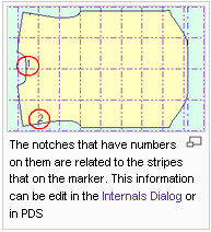
Notch and Point Numbers |
Determines whether or not the Stripe Adjust Numbers will be displayed on the piece and will be plotted. To change the font size, change the marker font in the Fonts dialog.
|
|
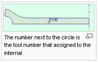
Tools/ Layers |
Determines whether or not the Tools or Layers will be displayed on the piece with output.
|
|
Internals by Tool |
|
|
Draw |
All internals that are drawn with the pen tool, or that was manually change to those commands, will be displayed and plotted with a common color |
|
Cut , Punch |
All internals that are cut with the cut tool , or that was manually change to those commands, will be displayed and plotted with a common color. |
|
Drill , Aux. Drill |
All buttons and notches that will be cut with the drill tool will be displayed with a common color |
|
Quality |
All internals that are defined with a Quality attribute and track lines will display an with a common color. Track lines will not be plotted |
|
Sew |
All internals that are defined as saw will displayed and plotted an with a common color |
|
None |
All internals that are defined with a None attribute will display with a common color |
|
Internals Section |
|
|
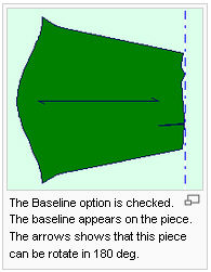
Baseline |
Determines whether or not the baseline will be displayed on the piece. If the baseline is displayed on the marker screen it will be plotted out in a drew mode |
|
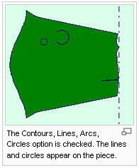
Contours, Lines, Arcs, Circles |
Determines whether or not two points line, draft lines, and circles will be displayed on the screen and on the plot |
|
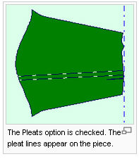
Pleats |
Determines whether or not the pleat and axis lines will be displayed on the pieces |
|
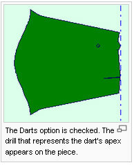
Darts |
Determines whether or not the dart point and dart beginning will be displayed on the pieces. OptiTex Marker will not display or output the fully drawn dart, only 2 notches and a drill hole in the dart's apex |
|
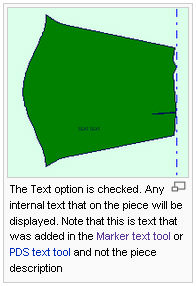
Text |
By selecting this option, you can determine whether or not internal text on a piece will be displayed. This text can be helpful when including last minute instructions to the operator. This does not affect the text that is part of the piece description.
|